
The SISCO RP1000D series high-voltage differential probes are compatible with general-purpose oscilloscopes. The specified attenuation ratio is calibrated for an oscilloscope input impedance of 1 MΩ. When the oscilloscope input impedance is set to 50 Ω, the attenuation doubles compared to that at 1 MΩ input impedance.
Safety, Durability, and Ease of Use for Long-Term Testing
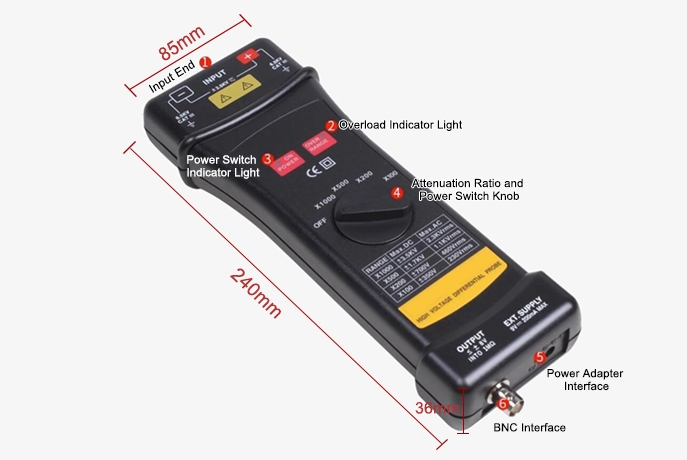
- Separating Design (Standard No.114205): Featuring a separating design for enhanced safety, the probe ensures electrical isolation and prevents unwanted interference in measurements.
- Convenient & Durable: Built for durability, the high-voltage differential oscilloscope probe is designed for long-lasting use and ease of handling, providing a reliable tool for high-voltage testing.
Performance and Versatility for High-Voltage Measurements
- Economical High Voltage Model: This probe offers a cost-effective solution for high-voltage differential measurements, making it ideal for both professional and educational use.
- 25MHz / 1400Vp-p Max: With a bandwidth of 25MHz and a maximum differential voltage of 1400Vp-p, it provides reliable performance for high-voltage signals in various applications.
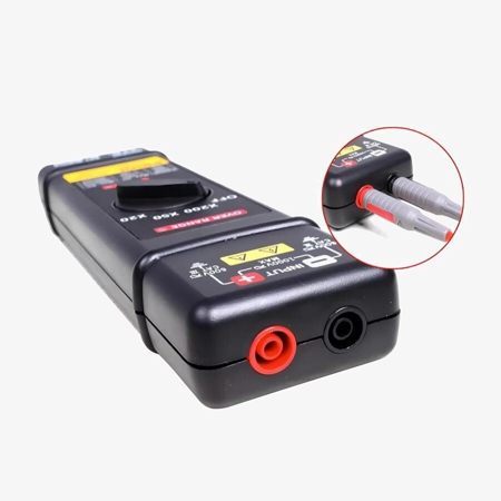
- x20 / x50 / x200 Attenuation Ratio: The probe features three selectable attenuation ratios (x20, x50, x200), ensuring versatility in measuring a wide range of voltage levels.
Applications
High voltage differential oscilloscope probes are essential tools for analyzing and troubleshooting a wide range of electronic systems, particularly those involving AC currents. Key applications include the testing and optimization of motor drives, where these probes facilitate precise measurement of current waveforms, enabling analysis of motor performance and efficiency. In power inverters and converters, these probes are crucial for verifying correct operation, identifying switching losses, and ensuring compliance with power quality standards. Similarly, in power supply design and testing, AC current probes provide vital insights into current draw, ripple current, and transient response. Furthermore, their high bandwidth and accuracy make them indispensable in avionics applications, where precise current measurements are critical for ensuring the reliability and safety of aircraft electrical systems.
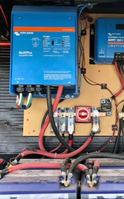
Power Inverters/Converters
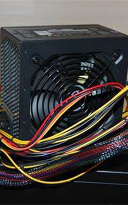
Power Supplies

Avionics
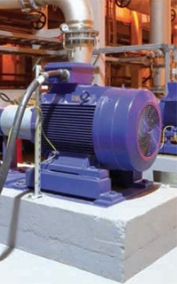
Motor Drives
| Model | SISCO-OP-RP1025D | SISCO-OP-RP1050D | SISCO-OP-RP1100D |
| Bandwidth | X50,X200: DC-25MHz(-3dB); X20: DC-15MHz |
X200,X500,X1000: DC-50MHz(-3dB); X100: DC-25MHz |
X200,X500,X1000: DC-100MHz(-3dB); X100: DC-50MHz |
| Attenuation Ratio | X20, X50, X200 | X100, X200, X500, X1000 | X100, X200, X500, X1000 |
| Accuracy | ±2% | ||
| Input Voltage Range (DC+AC peak-to-peak) | X20: ≤140Vpp, about 50Vrms or DC; X50: ≤350Vpp, about 125Vrms or DC; X200: ≤1400Vpp, about 500Vrms or DC |
X100: ≤700Vpp, about 230Vrms or DC; X200: ≤1400Vpp, about 460Vrms or DC; X500: ≤3500Vpp, about 1140Vrms or DC; X1000: ≤7000Vpp, about 2300Vrms or DC |
|
| Max Input Voltage | Max Differential Voltage: 1400V(DC+AC peak to peak) or 500Vrms; Input voltage to ground: 600Vrms |
Max Differential Voltage: 7000V(DC+AC peak to peak) or 2300Vrms; Input voltage to ground: 6500Vrms |
|
| Input Impedance | Differential: 4MΩ/1.2PF: Single-ended to ground: 2MQ/2.3pF |
Differential: 100MΩ/1.2PF; Single-ended to ground: 50MΩ/2.3pF |
|
| Output Voltage | ≤±6.5V | ≤±7V | ≤±8V |
| Output Impedance | 50Ω | ||
| Rise Time | X50,X200: 14ns; X20: 23.4ns |
X200,X500,X1000: 7ns; |
X200,X500,X1000: 3.5ns; X100: 7ns |
| Common Mode Rejection | 60Hz: >80dB, 100Hz: >60dB, 1MHz: >50dB | ||
| Power Supply | External 9V DC power supply | ||
| Power Consumption | 0.4 watt | ||
| Probe Size | 214mmx60mmx35mm | 240mmx85mmx36mm | |
| Weight | 280g | ||
| Safety | IEC1010-1, CAT III, Pollution Degree:2 | ||
| Electromagnetic Compatibility | Complies with EN50081-1 and 50082-1 standards | ||
| Max Voltage to Ground | 600Vrms | 6500Vrms | |
| Use Environment | Indoor | ||
| Insulation Category | Double insulation | ||
| Operating Environment | |||
| General | Operate | Storage | |
| Temperature | +20°C to +30°C | 0℃ to +50℃ | -30℃ to +70℃ |
| Humidity | ≤70%RH | 10% to 85%RH | 10% to 90%RH |
Details
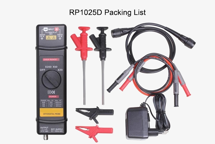
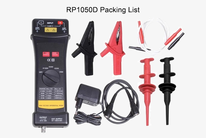
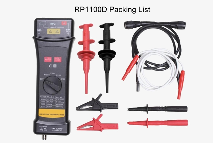
Packing List
Q1: What is probe attenuation?
A1: Probe attenuation refers to the reduction in the amplitude of the signal being measured by the oscilloscope probe. It is typically expressed as a ratio, such as 10X or 1X, indicating how much the signal is scaled down. For example, a 10X probe reduces the signal by a factor of 10, meaning the oscilloscope sees only one-tenth of the input signal’s voltage. Attenuation is useful for measuring higher voltage signals without overloading or damaging the oscilloscope, ensuring that the input signal is within the device's safe measurement range. It also improves the probe’s bandwidth and reduces the loading effect on the circuit under test.
Q2: How to minimize noise when using oscilloscope probes?
A2: To minimize noise when using oscilloscope probes, it's essential to ensure proper grounding, use short ground leads, and maintain good probe placement to reduce electromagnetic interference (EMI). Keep the probe tip as close as possible to the test point to minimize the probe's cable length, which can act as an antenna and pick up external noise. Additionally, use low-noise, shielded probes if possible and consider employing a differential probe for balanced measurements in noisy environments. Adjust the oscilloscope’s settings, such as averaging or filtering, to reduce noise in the displayed signal. It's also important to use the correct probe attenuation (e.g., 10X) to ensure the oscilloscope is properly scaled, and avoid using probes that might introduce excessive loading on the circuit, which can also contribute to noise.
Q3: What is the difference between a passive and active oscilloscope probe?
A3: A passive oscilloscope probe is a simple device that does not require an external power source to operate. It typically consists of a resistive voltage divider network, which attenuates the signal as it passes through the probe. Passive probes are commonly used for general-purpose measurements, offering a broad frequency range and a simple, cost-effective solution for many applications. They are typically lighter, more durable, and less expensive than active probes, making them a popular choice for basic signal testing. However, they can introduce a higher level of loading on the circuit under test, which may affect the accuracy of measurements, particularly at high frequencies.
An active oscilloscope probe, on the other hand, uses internal electronics, such as transistors or amplifiers, to actively measure and condition the signal. These probes require a power source, often provided through the oscilloscope itself. Active probes provide higher input impedance, lower capacitance, and reduced loading on the circuit, making them more suitable for high-speed or high-frequency applications where precision is critical. They can also handle higher voltage levels with better accuracy and stability, but they are typically more expensive and require additional components to operate. Active probes are ideal for advanced measurements, such as those in digital circuits or high-frequency signals, where low loading and high performance are essential.
Tips: how to use a high voltage differential probe?
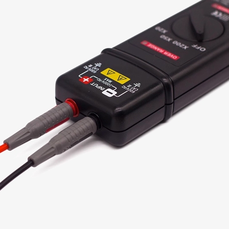
① Connect one end of the red safety IC clip to the red dual banana plug silicone wire, and one end of the black safety IC clip to the black dual banana plug silicone wire. Then, connect the red dual banana plug silicone wire to the red (+) input port of the high-voltage probe, and the black dual banana plug silicone wire to the black (-) input port of the high-voltage probe. Note: a) The safety IC clip can be replaced by a high-voltage-specific IC clip, a safety alligator clip, or a safety contact probe. b) The dual banana plug silicone wire can be replaced by a high-voltage-specific dual banana plug silicone wire.
② Connect one end of the BNC-to-BNC coaxial cable to the BNC interface of the high-voltage differential probe, and the other end to the oscilloscope input.
③ Turn on the channel switch on the oscilloscope, and adjust the high-voltage probe and oscilloscope to match their attenuation ratios. If the oscilloscope’s attenuation ratio does not match the high-voltage probe’s, the actual vertical scale will be the high-voltage probe’s attenuation ratio divided by the oscilloscope’s attenuation ratio, then multiplied by the vertical scale on the oscilloscope. For example: if the oscilloscope’s attenuation ratio is set to 1X, and the high-voltage probe’s attenuation ratio is set to X200, with the vertical scale on the oscilloscope set to 0.5V/div, the actual vertical scale will be 200 x 0.5V/div = 100V/div. When the oscilloscope’s input impedance is 50 Ω, the actual vertical scale will be 2 x 200 x 0.5V/div = 200V/div.
Note: When the oscilloscope’s attenuation ratio matches the high-voltage probe’s attenuation ratio, the vertical scale displayed on the oscilloscope will be the actual scale.
Thank you for buying industrial test and measurement equipment on SISCO.com, all products sold by SISCO and the partner cover a 12 months warranty, effective from the date of receiving the products.
What is covered?
SISCO is responsible for providing free spare parts, and free technical support to assist the customer to repair the defective products until the problem is solved.
What is not covered?
- Product purchased from anyone other than a SISCO store or a SISCO authorized reseller.
- Expendable parts.
- Routine cleaning or normal cosmetic and mechanical wear.
- Damage from misuse, abuse or neglect.
- Damage from use of parts other than SISCO approved.
- Damage from use outside the product’s usage or storage parameters.
- Damage from use of parts not sold by SISCO.
- Damage from modification or incorporation into other products.
- Damage from repair or replacement of warranted parts by a service provider other than a SISCO authorized service provider.
- Damage caused by the application environment not meeting the product usage requirements and the failure to perform preventive maintenance.

Shop on sisco.com for all of your industrial test and measurement equipment & accessories including portable detectors, meters, testers, scales, etc.


