
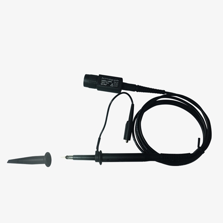
500 MHz oscilloscope probes professional and accurate measurements with stable performance, accompanied by various accessories that simplify probing and measurement tasks—an essential tool for instrument engineers.
Performance and Functionality
- Bandwidth: DC-500MHz, providing high-performance signal measurement across a wide frequency range.
- The P6139B features automatic identification, simplifying setup and ensuring compatibility with various oscilloscopes.
- Supports TekProbeTM Level II interface, automatically recognized by the oscilloscope.
Structure and Flexibility
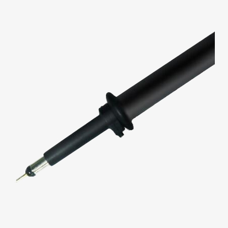
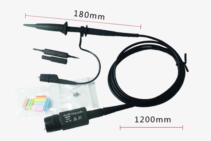
- Small probe tip: More suitable for accessing the tested circuit.
- Modular structure: The oscilloscope probes with the accessory kit are more flexible for use and adaptable to a wider range of testing scenarios.
Applications
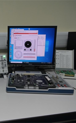
SISCO oscilloscope probes are essential tools for a variety of applications. They are widely used for signal measurement and analysis, allowing engineers to visualize and evaluate waveform characteristics like amplitude and frequency. In circuit debugging, these probes help identify faults, verify circuit performance, and compare actual waveforms with expected ones in real-time. During embedded systems development, oscilloscope probes are crucial for testing microcontrollers, processors, sensors, and other components by checking voltage levels and signal integrity. Additionally, oscilloscope probes play a key role in power electronics testing, enabling precise measurement of voltages and currents in applications such as inverters, power supplies, and motor control systems. These probes are indispensable for ensuring accurate analysis and troubleshooting in various electronic fields.
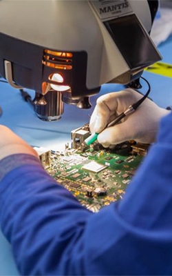
Circuit Debugging
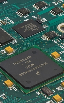
Embedded Systems Develop

Power Electronics Testing
Signal Measurement
| Model | SISCO-OP-P6139 | SISCO-OP-P6139A | SISCO-OP-P6139B |
| Attenuation | 10X / 1X | 10X | 10X |
| Bandwidth | 500MHz | ||
| Rise Time | <700Ps | ||
| Max Input Voltage | 300 VCATII | ||
| Input Resistance | 10MΩ /1MΩ | 10MΩ | 10MΩ |
| Input Capacitance | 11pF / 95pF | 9pF | 9pF |
| Auto-ID | NO | NO | YES |
| CableLength | 1.4m | ||
Details
Q1: What is probe attenuation?
A1: Probe attenuation refers to the reduction in the amplitude of the signal being measured by the oscilloscope probe. It is typically expressed as a ratio, such as 10X or 1X, indicating how much the signal is scaled down. For example, a 10X probe reduces the signal by a factor of 10, meaning the oscilloscope sees only one-tenth of the input signal’s voltage. Attenuation is useful for measuring higher voltage signals without overloading or damaging the oscilloscope, ensuring that the input signal is within the device's safe measurement range. It also improves the probe’s bandwidth and reduces the loading effect on the circuit under test.
Q2: How to minimize noise when using oscilloscope probes?
A2: To minimize noise when using oscilloscope probes, it's essential to ensure proper grounding, use short ground leads, and maintain good probe placement to reduce electromagnetic interference (EMI). Keep the probe tip as close as possible to the test point to minimize the probe's cable length, which can act as an antenna and pick up external noise. Additionally, use low-noise, shielded probes if possible and consider employing a differential probe for balanced measurements in noisy environments. Adjust the oscilloscope’s settings, such as averaging or filtering, to reduce noise in the displayed signal. It's also important to use the correct probe attenuation (e.g., 10X) to ensure the oscilloscope is properly scaled, and avoid using probes that might introduce excessive loading on the circuit, which can also contribute to noise.
Q3: What is the difference between a passive and active oscilloscope probe?
A3: A passive oscilloscope probe is a simple device that does not require an external power source to operate. It typically consists of a resistive voltage divider network, which attenuates the signal as it passes through the probe. Passive probes are commonly used for general-purpose measurements, offering a broad frequency range and a simple, cost-effective solution for many applications. They are typically lighter, more durable, and less expensive than active probes, making them a popular choice for basic signal testing. However, they can introduce a higher level of loading on the circuit under test, which may affect the accuracy of measurements, particularly at high frequencies.
An active oscilloscope probe, on the other hand, uses internal electronics, such as transistors or amplifiers, to actively measure and condition the signal. These probes require a power source, often provided through the oscilloscope itself. Active probes provide higher input impedance, lower capacitance, and reduced loading on the circuit, making them more suitable for high-speed or high-frequency applications where precision is critical. They can also handle higher voltage levels with better accuracy and stability, but they are typically more expensive and require additional components to operate. Active probes are ideal for advanced measurements, such as those in digital circuits or high-frequency signals, where low loading and high performance are essential.
Tips: how does a oscilloscope probe work?
An oscilloscope probe works by connecting to the circuit under test and capturing the electrical signals, which are then transmitted to the oscilloscope for analysis. The probe typically consists of a metal tip for probing the signal and a ground clip to establish a reference point. When the probe tip touches a circuit node, it measures the voltage at that point, and the signal is sent through a coaxial cable to the oscilloscope. Depending on the type of probe, the signal may be attenuated (scaled down) by a factor, such as 10X or 1X, to ensure the oscilloscope receives a signal within its measurable range. The oscilloscope then processes and displays the signal waveform, allowing users to analyze characteristics such as amplitude, frequency, and waveform shape. In active probes, internal electronics amplify or condition the signal to ensure minimal loading and higher accuracy, especially for high-speed or high-frequency measurements.
Thank you for buying industrial test and measurement equipment on SISCO.com, all products sold by SISCO and the partner cover a 12 months warranty, effective from the date of receiving the products.
What is covered?
SISCO is responsible for providing free spare parts, and free technical support to assist the customer to repair the defective products until the problem is solved.
What is not covered?
- Product purchased from anyone other than a SISCO store or a SISCO authorized reseller.
- Expendable parts.
- Routine cleaning or normal cosmetic and mechanical wear.
- Damage from misuse, abuse or neglect.
- Damage from use of parts other than SISCO approved.
- Damage from use outside the product’s usage or storage parameters.
- Damage from use of parts not sold by SISCO.
- Damage from modification or incorporation into other products.
- Damage from repair or replacement of warranted parts by a service provider other than a SISCO authorized service provider.
- Damage caused by the application environment not meeting the product usage requirements and the failure to perform preventive maintenance.

Shop on sisco.com for all of your industrial test and measurement equipment & accessories including portable detectors, meters, testers, scales, etc.


