
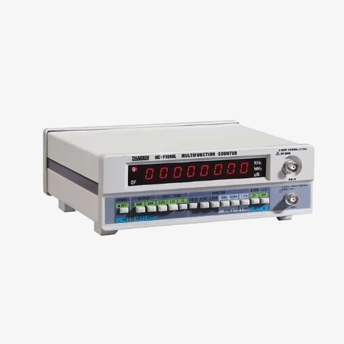
SISCO 8-digit frequency counter's high accuracy, sensitivity, small size, light weight, and high stability crystal oscillator to ensure measurement accuracy and full input signal inspection make it a very valuable tool for scientists, engineers, experimenters and communications technicians. Its light weight and compact size make it ideal for use by the hobbyist or field technician.
Multi-Function LCD Frequency Counter with High Resolution
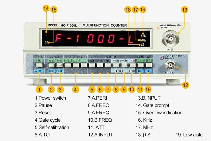
- 8-digit high-resolution seven-segment LED display.
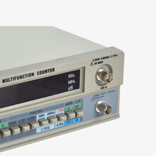
- Frequency measurement range: A input: 1Hz-100MHz; C input: 100MHz-1GHz.
- Period, Total and Resonator measurement functions: These functions expand the application range of the instrument, making it not only used for frequency measurement, but also for analyzing the periodicity of signals.
Self-Check and Filter Options Frequency Counter
- Multiple gate time selection: Select a longer gate time to improve measurement accuracy or a shorter gate time to speed up measurement as needed.
- Self-check function: The freq counter has a built-in self-check function, which can automatically perform a system check at startup to ensure that all functions and components are working properly.
Applications
SISCO frequency counters are widely used in general testing in R&D laboratories, quality control and inspection, device or circuit characterization and fault diagnosis, educational experiments, and production automation testing. In R&D and education, they help with signal measurement and analysis; in quality control, they ensure products meet standards; in fault diagnosis, they quickly identify issues; and in production, they monitor parameters in real-time to ensure production efficiency and product quality.
Comm. & Elec. Engineering

Research and Laboratory

Aerospace

Industry and Manufacturing
| Model | SISCO-HC-F1000L | |
| Measuring Mode | ||
| CHANNEL A | ||
| Range | 10Hz~10MHz (direct counting) 10MHz~100MHz (proportional counting) |
|
| Resolution | Direct counting: 1Hz, 10 Hz, 100Hz (optional) Proportional counting: 10 Hz, 100Hz, 1000Hz (optional) |
|
| Gate Time | 0.01s/0.1s/1s selectable | |
| Accuracy | ±1count ±time base error x frequency | |
| CHANNEL B | ||
| Range | 100MHz-1GHz | |
| Resolution | 100Hz, 1KHz, 10KHz | |
| Gate Time | 0.01s/0.1s/1s selectable | |
| Accuracy | ±1count ±time base error x frequency | |
| Period Measurement | ||
| Input | Channel A | |
| Range | 10Hz-10MHz | |
| Resolution | 10-7, 10-8, 10-9 selectable | |
| Accuracy | ±1count ±time base error x frequency | |
| Display | 8-digit digital tube 0-9 characters displayed repeatedly at the same time | |
| Cumulative Measurement | ||
| Input | Channel A | |
| Range | 10Hz-10MHz | |
| Resolution | TCO(temperature controlled oscillator) | |
| Frequency | 10.000000MHz | |
| Input Characteristics | ||
| CHANNEL A | ||
| Input Sensitivity | 10MHz |
10Hz~8MHz, 35mVrms |
|
8MHz~10MHz, 35mVrms |
||
| 100MHz | 10Hz~8MHz, 35mVrms | |
| 80MHz~100MHz, 35mVrms | ||
| Attenuation | x 1, x 20 fixed | |
| Filter (CH-A only) | Low pass | ~100KHz~3dB |
| ~150KHz~3dB at 20dB ATT | ||
| Impedance | Approx. 1MΩ , <3pF | |
| Max Voltage Without Damage | 250Vrms (DC+AC) | |
| CHANNEL B | ||
| Input Sensitivity | 20mVrms | |
| Impedance | Approx. 50Ω | |
| Max Voltage Without Damage | 3V | |
| Time Base | ||
| Frequency | 10MHz | |
| Short-Term Stability | ± 3x10⁻⁹ / second | |
| Long-Term Stability | ± 2x10⁻⁵ / month | |
| Temperature Coefficient | ± 1x10⁻⁵ / , 0 °C ~40°C | |
| General | ||
| Display | 8 digit 7mm red LED display with decimal point, gate, overflow, kHz, MHz and µs indication | |
| Check | Counts internal 10MHz time base oscillator | |
| Power Requirement | Line 115/230V ± 15% 45Hz~70Hz | |
| Warm-Up Time | 20 mins when cold started at 25 °C | |
| Temperature | Operation: 5 °C ~ +50 °C | |
| Storage and Transport Temperature | -40°C ~ +60°C | |
| Humidity | Operation: 10 ~ 90%RH | |
| Storage: 5~95%RH | ||
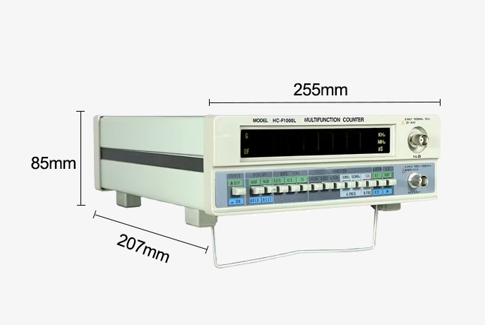
| Dimension | 207mm(H) X 85mm(W) X 255mm(D) | |
| Weight | 2kg | |
Dimensions (mm)
Details
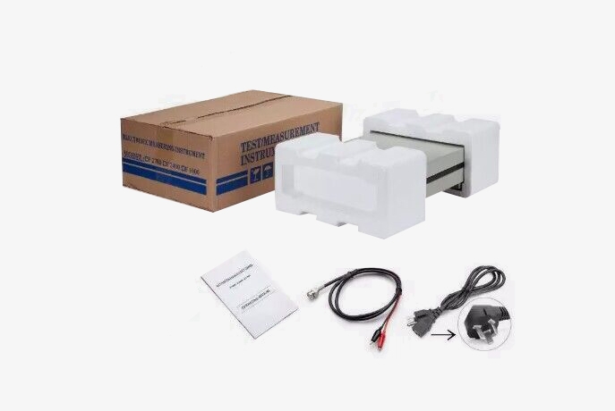
Packing List
- 1 x Frequency counter
- 1 x Power cord
- 1 x Fuse
- 1 x Test cable
- 1 x User manual
Q1: What factor most affects the accuracy of a frequency counter?
A1: The factor that most affects the accuracy of a frequency counter is the quality and stability of the time base oscillator. The time base oscillator provides the reference frequency against which the input signal is measured. High-quality oscillators, such as temperature-compensated crystal oscillators (TCXOs) or oven-controlled crystal oscillators (OCXOs), offer better stability, thus providing higher measurement accuracy. Additionally, the aging effect of the oscillator, as well as phase noise and jitter, can also impact measurement accuracy. Regular calibration of the frequency counter to compensate for any drift in the oscillator frequency is crucial for maintaining high accuracy.
Q2: What is the gate time of a frequency counter?
A2: The gate time of a frequency counter is the duration during which the instrument counts the number of cycles of the input signal to determine its frequency. Essentially, it defines the time interval over which the measurement is averaged, directly impacting both the resolution and accuracy of the measurement. A longer gate time results in higher resolution and more accurate frequency measurements, as it averages out short-term fluctuations and noise in the signal. However, it also means that measurements take longer to complete. Conversely, a shorter gate time allows for faster measurements but with lower resolution and potentially higher uncertainty. The choice of gate time is often a trade-off between the desired measurement accuracy and the required speed of measurement.
Q3: What types of signals can a frequency counter measure?
A3: A frequency counter can measure various types of signals, including sine waves, square waves, pulse trains, and other periodic waveforms. It is capable of measuring both analog and digital signals, making it versatile for applications in different fields. The counter can handle a wide range of frequencies, from very low frequencies (in the hertz range) to very high frequencies (in the gigahertz range), depending on the specific model and its input capabilities. Additionally, advanced frequency counters can measure parameters such as signal period, total event counts, and even the rotational speed of mechanical systems when equipped with the appropriate sensors. This versatility allows frequency counters to be used in telecommunications, electronics, industrial automation, and scientific research.
Tips: How to calculate a frequency counter?
To calculate the frequency of a signal using a frequency counter, follow these steps:
1. Set Up the Frequency Counter: Connect the input signal to the frequency counter and select the appropriate input range and mode for the type of signal being measured.
2. Choose the Gate Time: Select the gate time (or integration time) on the frequency counter. This is the duration over which the counter will measure the number of cycles of the signal. Longer gate times provide higher accuracy but take more time to measure.
3. Start the Measurement: Initiate the measurement process. The frequency counter will begin counting the number of cycles or events of the input signal during the gate time.
4. Calculate the Frequency: The frequency counter computes the frequency using the formula:
Frequency = Number of Cycles / Gate Time
Here, "Number of Cycles" is the count of signal cycles detected during the gate time, and "Gate Time" is the duration for which the counting occurred.
5. Display the Result: The frequency counter will display the calculated frequency, often in hertz (Hz), on its screen.
For example, if a frequency counter counts 10,000 cycles over a gate time of 1 second, the calculated frequency is:
Frequency = 10,000/1 = 10,000Hz or 10 kHz
This process allows the frequency counter to provide an accurate measurement of the signal's frequency based on the counted cycles and the specified gate time.
Thank you for buying industrial test and measurement equipment on SISCO.com, all products sold by SISCO and the partner cover a 12 months warranty, effective from the date of receiving the products.
What is covered?
SISCO is responsible for providing free spare parts, and free technical support to assist the customer to repair the defective products until the problem is solved.
What is not covered?
- Product purchased from anyone other than a SISCO store or a SISCO authorized reseller.
- Expendable parts.
- Routine cleaning or normal cosmetic and mechanical wear.
- Damage from misuse, abuse or neglect.
- Damage from use of parts other than SISCO approved.
- Damage from use outside the product’s usage or storage parameters.
- Damage from use of parts not sold by SISCO.
- Damage from modification or incorporation into other products.
- Damage from repair or replacement of warranted parts by a service provider other than a SISCO authorized service provider.
- Damage caused by the application environment not meeting the product usage requirements and the failure to perform preventive maintenance.

Shop on sisco.com for all of your industrial test and measurement equipment & accessories including portable detectors, meters, testers, scales, etc.


