SISCO three phase smart harmonic power analyzer can simultaneously measure 4 currents (ABC three-phase and neutral current), 4 voltages (ABC three-phase voltage and neutral voltage to ground), current and voltage peaks, maximum and minimum values within a period of time, three-phase unbalance, short-term voltage flicker, transformer K factor, active power, reactive power, apparent power, power factor, displacement power factor, active energy, reactive energy, apparent energy, harmonic ratio, total harmonic distortion, etc.
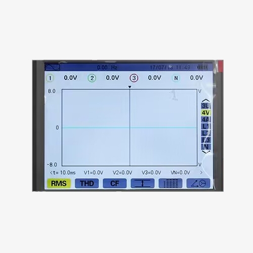
Versatile and Reliable Power Quality Monitoring System
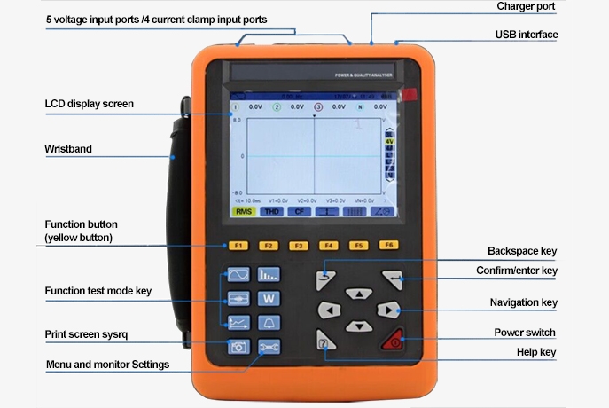
- Large color LCD display with high definition display and character function display.
- With communication software, the stored data can be uploaded to the computer for easy reading, saving, printing, etc.
- Real-time waveform display (4 voltages/4 currents): enabling users to observe dynamic characteristics and transient behaviors of the power system.
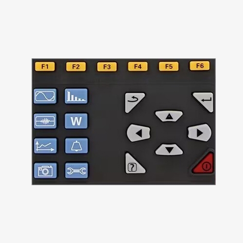
Harmonic Measurement & Customizable Display with Screen Capture
- Measurement of harmonics of each phase, up to 50th harmonics: to assess harmonic distortion within the power system.
- Screen capture function: Users can take a screenshot to store the current screen image on any test page, and automatically save the recording time and test mode.
- Setting function: Users can set the time and date, set the display contrast and brightness, set the corresponding color of each phase waveform curve in the instrument, etc.
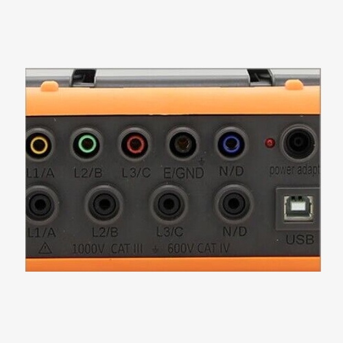
USB Connectivity and Data Logging
- Top USB port: Equipped with USB port to realize computer communication function.
- The 2G memory card is used to store long-term trend curve records and 20 power parameters at the same time (optional) and can record and store trend curve records for up to 300 days.
- 12800 sets of alarm logs, the starting current detection mode can continuously capture the starting current waveform for 100s.
Applications
SISCO power quality analysers are applicable to electric power, petrochemical, metallurgy, railway, industrial and mining enterprises, scientific research institutions, measurement departments, etc. Especially suitable for comprehensive analysis and diagnosis of all voltage, current, power, electric energy, harmonics, phase and other electrical parameters. It is also applicable to various power systems to timely discover problems in the power system, avoid power loss, and achieve energy saving and loss reduction.

Metallurgy

Petrochemicals

Railways
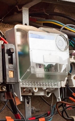
Electricity
| Model | SISCO-PQA-VC5000 | ||
| Basic Functions | Measuring Range | Display Resolution | Maximum Error Within the Reference Range |
| Frequency | 40Hz~70Hz | 0.01Hz | ±(0.03)Hz |
| Phase Voltage True RMS | 1.0V~1000V | Minimum resolution 0.1V | ±(0.5%+5dgt) |
| Line Voltage True RMS | 1.0V~2000V | Minimum resolution 0.1V | ±(0.5%+5dgt) |
| DC Voltage | 1.0V~1000V | Minimum resolution 0.1V | ±(1.0%+5dgt) |
| Current True RMS | 10mA~3000A | Minimum resolution 1mA | ±(0.5%+5dgt) |
| Phase Voltage Peak | 1.0V~1414V | Minimum resolution 0.1V | ±(1.0%+5dgt) |
| Line Voltage Peak | 1.0V~2828V | Minimum resolution 0.1V | ±(1.0%+5dgt) |
| Current Peak | 10mA~4200A | Minimum resolution 1mA | ±(1.0%+5dgt) |
| Crest Factor | 1.00~3.99; 4.00~9.99 | 0.01; 0.01 | ±(1%+2dgt) |
| Active Power | 0.000W~9999.9kW | Minimum resolution 0.001W | ±(1%+3dgt) |
| Reactive Power Inductive & Capacitive | 0.000VAR~9999.9kVAR | Minimum resolution 0.001VAR | ±(1%+3dgt)Cosφ≥0.8; ±(1.5%+10dgt)0.2≤Cosφ<0.8 |
| Apparent Power | 0.000VA~9999.9kVA | Minimum resolution 0.001VA | ±(1%+3dgt) |
| Power Factor | -1.000~1.000 | 0.001 | ±(1.5%+3dgt)Cosφ≥0.5 |
| Active Energy | 0.000Wh~9999.9MWh | Minimum resolution 0.001Wh | ±(1%+3dgt)Cosφ≥0.8 |
| Reactive Energy Inductive & Capacitive | 0.000VARh~9999.9MVARh | Minimum resolution 0.001VARh | ±(1%+3dgt)Sinφ≥0.5; ±(1.5%+10dgt)0.2≤Sinφ<0.5 |
| Apparent Energy | 0.000VAh~9999.9MVAh | Minimum resolution 0.001VAh | ±(1%+3dgt) |
| Phase Angle | -179°~180° | 1° | ±(2°) |
| Tanφ(VA≥50VA) | -32.76~32.76 | Minimum resolution 0.001 | φ:±(1°) |
| Displacement Power Factor (DPF) | -1.000~1.000 | 0.001 | φ:±(1°) |
| Harmonic Ratio (including 1st to 50th) (Vrms>50V) | 0.0%~99.9% | 0.10% | ±(1%+5dgt) |
| Harmonic Angle (Vrms>50V) | -179°~180° | 1° | ±(3°) Harmonic 1 to 25 |
| Total Harmonic Rate (THD or THD-F) ≤ 50 | 0.0%~99.9% | 0.10% | ±(1%+5dgt) |
| Distortion Factor (DF or THD-R) ≤ 50 | 0.0%~99.9% | 0.10% | ±(1%+10dgt) |
| Transformer K Factor | 1.00~99.99 | 0.01 | ±(5%) |
| Three-Phase Unbalance | 0.0%~100% | 0.10% | ±(1%) |
| General Features | |||
| Power Supply | Rechargeable lithium battery pack 9.6V (not includind), external charger | ||
| Battery Level Indicator | The battery symbol has 5 grids to show the battery level. When the battery level is too low, the device will automatically shut down after 1 minute. | ||
| Working Current | About 490mA, the battery is fully charged and can work continuously for about 8 hours | ||
| Display Mode | LCD color screen, 640 dots × 480 dots, 5.6 inches, display area 116 mm × 88 mm | ||
| Clamp(optional) Size | 008B pointed current clamp: 7.5mm×13mm; 040B round current clamp: 35mm×40mm; 068B round current clamp: 68mm×68mm; 300F flexible coil current sensor (with integrator): Φ300mm | ||
| Instrument Size | Length, width and thickness: 240mm×170mm×68mm | ||
| Number of Channels | 4 voltage channels, 4 current channels | ||
| Line Voltage | 1.0V~2000V | ||
| Phase Voltage | 1.0V~1000V | ||
| Current | 008B current clamp: 10mA~10.0A; 040B current clamp: 0.10A~100A; 068B current clamp: 1.0A~1000A; 300F flexible coil current sensor (with integrator) 10A~3000A | ||
| Power Quantity Parameters | W, VA, Var, PF, DPF, cosφ, tanφ | ||
| Power Parameters | Wh, Varh, Vah | ||
| Harmonic | 0-50 times | ||
| Total Harmonic Distortion | 0 to 50 times, each phase | ||
| Expert Mode | √ | ||
| Number of Transient Record Groups | 150 groups | ||
| Voltage Flicker | √ | ||
| Start-Up Current Mode | 100 seconds | ||
| Record | 300 days (recording 20 parameters simultaneously, 1 point every 5 seconds) | ||
| Minimum and Maximum Recorded Values | Can measure the maximum and minimum values within a period of time | ||
| Alerts | 40 different types of parameter selection, 12,800 groups of alarm logs | ||
| Peak | √ | ||
| Screenshot Capacity | 60 SETs | ||
| Menu Language | Chinese, English | ||
| Communication Interface | USB | ||
| Auto Shutdown | In alarm/trend chart recording/transient capture mode (waiting or in progress), the instrument does not automatically shut down | ||
| In other test modes, if there is no key operation within 15 minutes, the machine will automatically shut down after 1 minute. | |||
| Backlight | √, Suitable for dimly lit places and night use | ||
| Instrument Quality | Main unit: 1.6kg (with battery); | ||
| 008B small pointed current clamp: 170g×4; | |||
| 040B round mouth current clamp: 190g×4; | |||
| 068B round mouth current clamp: 510g×4; | |||
| 300F flexible coil current sensor (with integrator): 330g×4; | |||
| Test lead and power adapter: 900g; | |||
| Voltage Test Line Length | 3m | ||
| Current Clamp Wire Length | 2m | ||
| Working Temperature and Humidity | -10℃~40℃; below 80%Rh | ||
| Storage Temperature and Humidity | -10℃~60℃; below 70%Rh | ||
| Input Impedance | Test voltage input impedance: 1MΩ | ||
| Pressure Resistance | The instrument circuit and the housing withstand a 3700V/50Hz sine wave AC voltage for 1 minute | ||
| Insulation | Between the instrument circuit and the sheath shell ≥10MΩ | ||
| Structure | Double insulation, with insulating anti-vibration sheath | ||
| Safety Regulations | IEC 61010 1000V Cat III / 600V CAT IV, IEC61010-031, IEC61326 Pollution Degree 2 | ||
Details
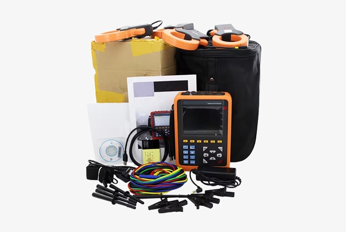
Packing List
- 1 x Color box
- 1 x Charger
- 4 x Current clamp (selectable)
- 1 x Instruction manual
- 1 x Instrument bag
- 1 x Certificate of conformity
- 1 x Host
- 1 x Software CD
- 1 x USB cable
- 1 x Carrying strap
- 5 x Test probe
- 5 x Test lead
- 5 x Alligator clip
Q1: What types of data can a power quality analyzer log?
A1: A power quality analyzer can log a variety of data related to electrical systems' performance. This includes voltage and current waveforms, harmonic distortion, frequency deviations, power factor, transient events, and fluctuations in load. It can capture detailed information on voltage sags, swells, and spikes, as well as track steady-state data such as maximum, minimum, and average values over specified intervals. Additionally, it can record event-triggered data with customizable thresholds and analyze power quality issues in real-time or over extended periods, providing insights into both immediate disturbances and long-term trends.
Q2: How does a power quality meter detect disturbances?
A2: A power quality meter detects disturbances by continuously monitoring electrical signals and comparing them to predefined thresholds and standards. It analyzes deviations in voltage, current, and frequency, capturing and recording anomalies such as sags, swells, harmonics, and transients. The meter processes these deviations to identify patterns or irregularities that indicate potential issues, providing real-time alerts and logging detailed data for further analysis. This allows for precise diagnosis of power quality problems and helps in troubleshooting and maintaining the reliability of electrical systems.
Q3: What are harmonic distortions?
A3: Harmonic distortions refer to deviations from the ideal sinusoidal waveform of electrical signals caused by non-linear loads, such as electronic devices, fluorescent lighting, and variable speed drives. These distortions introduce additional frequencies, known as harmonics, into the power system, which are integer multiples of the fundamental frequency. Harmonic distortions can lead to problems such as overheating of equipment, reduced efficiency, increased losses, and interference with sensitive electronic devices. Identifying and mitigating harmonic distortions is crucial for maintaining the health and performance of electrical systems.
Tips: How does a harmonic power analyzer work?
A harmonic power analyzer measures and analyzes the harmonic distortion in electrical power systems. It works by decomposing the electrical signals into their fundamental frequency and harmonic components using Fourier transform techniques. The analyzer captures voltage and current waveforms and then calculates the harmonic content, which includes higher frequency components that are integer multiples of the fundamental frequency. By assessing the amplitude and phase of these harmonics, the analyzer helps in evaluating power quality, identifying sources of distortion, and ensuring compliance with standards to improve the efficiency and reliability of the power system.
Thank you for buying industrial test and measurement equipment on SISCO.com, all products sold by SISCO and the partner cover a 12 months warranty, effective from the date of receiving the products.
What is covered?
SISCO is responsible for providing free spare parts, and free technical support to assist the customer to repair the defective products until the problem is solved.
What is not covered?
- Product purchased from anyone other than a SISCO store or a SISCO authorized reseller.
- Expendable parts.
- Routine cleaning or normal cosmetic and mechanical wear.
- Damage from misuse, abuse or neglect.
- Damage from use of parts other than SISCO approved.
- Damage from use outside the product’s usage or storage parameters.
- Damage from use of parts not sold by SISCO.
- Damage from modification or incorporation into other products.
- Damage from repair or replacement of warranted parts by a service provider other than a SISCO authorized service provider.
- Damage caused by the application environment not meeting the product usage requirements and the failure to perform preventive maintenance.

