
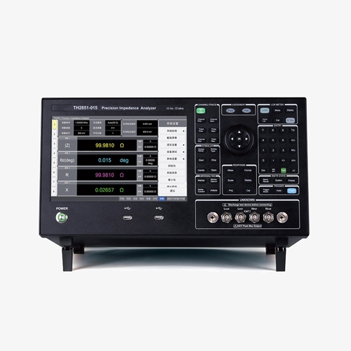
The SISCO high frequency LCR impedance analyzer features a trajectory noise level of ≤0.003%, making it ideal for measuring various components, including passive and semiconductor elements.
High-Speed, High-Precision Impedance Testing with Three Methods
- Three test methods: point test, list scan, and graph scan.
- High speed LCR impedance analyzer: the fastest test speed up to 5ms.
- High precision LCR impedance analyzer: using automatic balance bridge technology, four-terminal pair test confguration.
Multi-Parameter Scanning with High-Resolution Display
- 1601 point multi-parameter list scanning function.
- High resolution: 10.1-inch capacitive touch screen, resolution 1280*800.
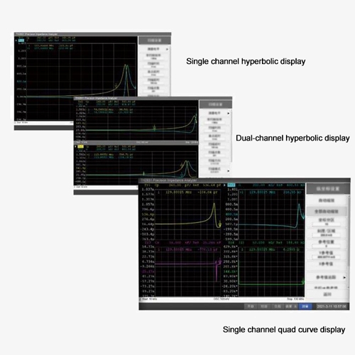
- 4-channel graphic scanning function, each channel can display 4 curves, 16 kinds of split-screen display modes for channels and curves.
Powerful 10-Grade Sorting and High Compatibility
- Powerful sorting: 10-grade sorting, sorting results are displayed on the main interface, convenient for users to select.
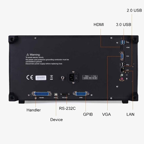
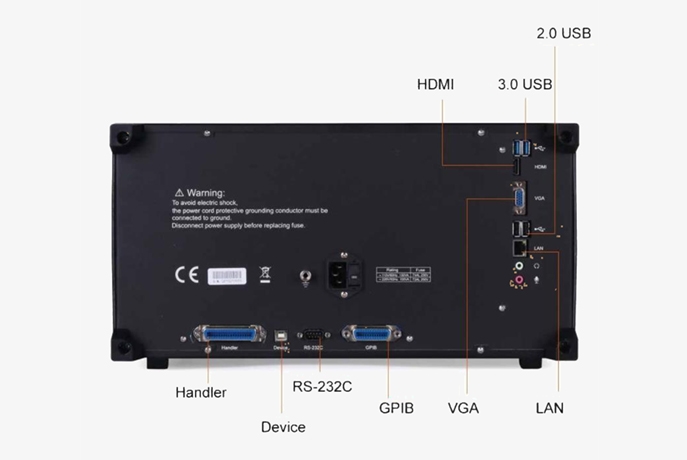
- High compatibility: Interfaces such as RS232C, USB HOST, USB DEVICE, LAN, GPIB, HANDLER, VGA, and HDMI support the SCPI command set, making them compatible with devices E4990A, E4980A, E4980AL, and HP4284A.
Applications
The SISCO precision LCR impedance analyzer is designed for evaluating the impedance parameters and performance of various components such as capacitors, inductors, printed circuit boards, and cables. It is also capable of analyzing the C-VDC characteristics of varactor diodes. Additionally, the analyzer is suitable for assessing different materials, including dielectric, magnetic, semiconductor materials, and liquid crystal units, making it a versatile tool for both component and material analysis.

Magnetic Materials
Semiconductor Materials

Liquid Crystal Cell
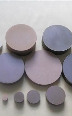
Dielectric Materials
| Model | SISCO-IA-TH2851-015 | SISCO-IA-TH2851-030 | SISCO-IA-TH2851-050 | SISCO-IA-TH2851-080 | SISCO-IA-TH2851-130 | |
| Display | 10.1 Inches TFT LCD Display 1280×RGB×800, Touch Screen | |||||
| AC Parameter | Cp/Cs, Lp/Ls, Rp/Rs, |Z|, |Y|, R, X, G, B, θ, D, Q, VAC, IAC | |||||
| DC Parameter | DCR, VDC, IDC | |||||
| Test Frequency | Range | 10Hz-15MHz | 10Hz-30MHz | 10Hz-50MHz | 10Hz-80MHz | 10Hz-130MHz |
| Resolution | 1mHz | |||||
| Relative Frequency Tolerance | ≤±0.0007% | |||||
| Test Level | AC Voltage | 5mV-2Vrms | ||||
| Resolution | 1mV | |||||
| AC Current | 50uA-20mArms | |||||
| Resolution | 10uA | |||||
| DC Bias | Voltage | 0V - ±40V | ||||
| Resolution | 1mV | |||||
| Current | 0mA - ±100mA | |||||
| Resolution | 40μA | |||||
| Test Terminal Configuration | Four terminal pair | |||||
| Output Impedance | 25Ω / 100Ω | |||||
| Typical Test Time (Speed) | Five Shift: 1 (Fast)—5 (Accuracy) 1: 2.5ms; 2: 10ms; 3: 40ms; 4: 80ms; 5: 400ms (Does not include the arithmetic average of the communication time, each frequency test speed will be slightly different) |
|||||
| Max Accuracy | 1kHz: 0.08% 1MHz: 0.08% 2MHz: 0.5% 10MHz: 1% 130MHz: 5.0% |
|||||
| Test Display Range | E: 1×10¹⁸ | |||||
| Cs、Cp | -9.99999EF ~ +9.99999EF | |||||
| Ls、Lp | -9.99999EH ~ +9.99999EH | |||||
| D | -9.99999E ~ +9.99999E | |||||
| Q | -9.99999E ~ +9.99999E | |||||
| R, Rs, Rp, X, Z, RDC | -9.99999EΩ ~ +9.99999EΩ | |||||
| G, B, Y | -9.99999ES ~ +9.99999ES | |||||
| Vdc | -9999V ~ +9999V | |||||
| Idc | -9999mA ~ +9999mA | |||||
| θr | -999999rad ~ +999999rad | |||||
| θd | -180.0deg ~ +180.0deg | |||||
| Δ% | -999999% ~ +999999% | |||||
| Multi-Function Parameter List Scan | 1601 points, each point can be set to average, and each point can be sorted separately Sweep parameters: measurement parameters, test frequency, AC voltage, AC current, DC BIAS voltage, DC BIAS current | |||||
| Graphic Scan | Parameter | Frequency, ACV, ACI, DCV, DCI | ||||
| Types | Logarithmic, linear, frequency segmentation | |||||
| Points | 2-1601 | |||||
| Number of Channels | 4 | |||||
| Number of Curves | 4 / Per channel | |||||
| Split Screen | 14 (Channel and Curve) | |||||
| Equivalent Circuit Analysis | 3-element model: 4 4-element model: 3 |
|||||
| Sorting | 10 levels of sorting in LCR mode; each curve in scan mode is sorted individually | |||||
| Interface | RS232C, USB HOST, USB DEVICE, LAN, GPIB, HANDLER, VGA, HDMI | |||||
| Power-On Warm-Up Time | 60 Minutes | |||||
| Input Voltage | 100-120VAC/198-242VAC Option, 47-63Hz | |||||
| Power Consumption | Max 150VA | |||||
| Measurement (WxHxD) MM3 | 428x220x325 | |||||
| Weight | 14.5kg | |||||
Details
Q1: What is the difference between impedance analyzer and network analyzer?
A1: An impedance analyzer and a network analyzer both measure electrical characteristics, but their functions and applications differ significantly. An impedance analyzer focuses on measuring the impedance of individual components or materials, typically over a wide frequency range, and can analyze parameters like inductance, capacitance, and resistance. It is primarily used for detailed component testing, material characterization, and low-frequency circuit analysis.
In contrast, a network analyzer measures the scattering parameters (S-parameters) of electrical networks or circuits, which describe how radio frequency (RF) signals behave as they pass through the network. It is typically used for high-frequency applications, such as testing antennas, RF circuits, and microwave systems. A network analyzer provides insights into how signals reflect, transmit, or are absorbed by a device under test, making it more suited for system-level analysis in telecommunications and signal processing.
In summary, impedance analyzers are used for component-level testing at various frequencies, while network analyzers are essential for analyzing signal behavior in RF and microwave systems.
Q2: What factors can affect impedance measurements?
A2: Impedance measurements can be affected by several factors, including the frequency of the test signal, as impedance varies with frequency, especially in reactive components like inductors and capacitors. Poor test leads and connections can introduce parasitic effects, skewing results. Temperature changes can alter the electrical properties of materials, impacting resistance and reactance. The amplitude of the test signal is also critical, as some components exhibit non-linear behavior at different signal levels. Environmental factors like electromagnetic interference (EMI) and component aging or tolerances can further distort accurate readings, making it essential to control these variables during measurement.
Q3: What is the typical output format of an impedance analyzer?
A3: The typical output format of an impedance analyzer includes a combination of impedance magnitude and phase angle, often represented as a complex number or polar coordinates. The results can also be presented as real and imaginary components of impedance, or converted into related parameters like resistance (R), reactance (X), capacitance (C), and inductance (L). In addition, some impedance analyzers offer graphical outputs, such as Nyquist plots or Bode plots, showing impedance as a function of frequency. The output is usually provided digitally through a display, and many devices support exporting data in formats like CSV for further analysis.
Tips: How does a impedance analyzer work?
An impedance analyzer works by applying an AC signal to a component or circuit and then measuring its response to determine its impedance, which is the opposition to alternating current flow. The analyzer generates a test signal at a specific frequency and amplitude, then measures the voltage and current through the component under test. By calculating the ratio of voltage to current, it determines the impedance, which can be represented as both magnitude and phase. Advanced impedance analyzers can sweep across a range of frequencies to assess impedance characteristics over a spectrum, providing data on resistance, reactance, capacitance, and inductance. These measurements are often visualized in various plots, like Nyquist or Bode diagrams, and the data can be exported for further analysis.
Thank you for buying industrial test and measurement equipment on SISCO.com, all products sold by SISCO and the partner cover a 12 months warranty, effective from the date of receiving the products.
What is covered?
SISCO is responsible for providing free spare parts, and free technical support to assist the customer to repair the defective products until the problem is solved.
What is not covered?
- Product purchased from anyone other than a SISCO store or a SISCO authorized reseller.
- Expendable parts.
- Routine cleaning or normal cosmetic and mechanical wear.
- Damage from misuse, abuse or neglect.
- Damage from use of parts other than SISCO approved.
- Damage from use outside the product’s usage or storage parameters.
- Damage from use of parts not sold by SISCO.
- Damage from modification or incorporation into other products.
- Damage from repair or replacement of warranted parts by a service provider other than a SISCO authorized service provider.
- Damage caused by the application environment not meeting the product usage requirements and the failure to perform preventive maintenance.

Shop on sisco.com for all of your industrial test and measurement equipment & accessories including portable detectors, meters, testers, scales, etc.


