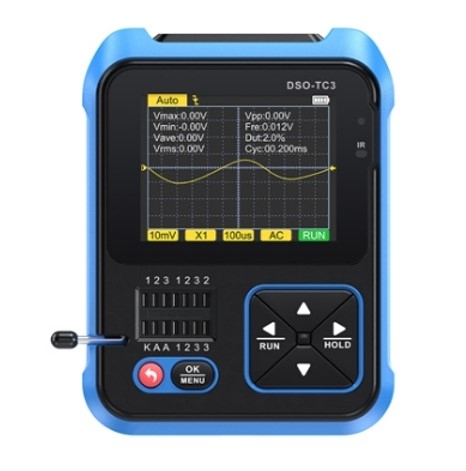
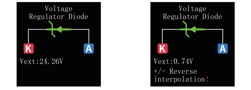
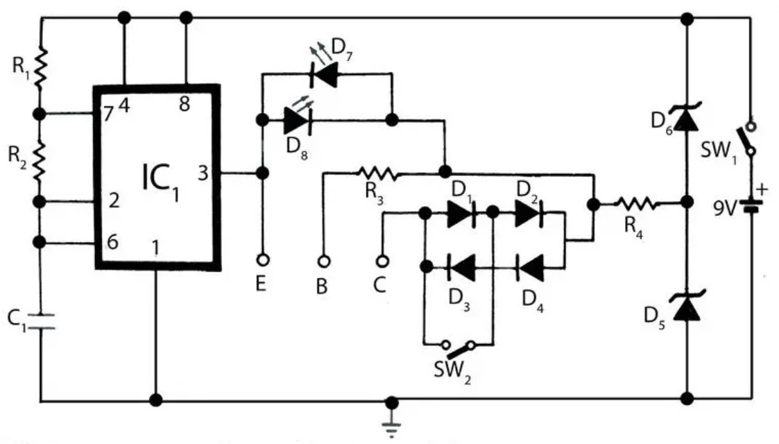
Transistor tester is electronic instruments, which based on general electronic measuring instruments and measuring semiconductor devices. It can be used to test the input and output characteristics of the common emitter and common base circuits of transistor (NPN and PNP); Test various reverse saturation currents and breakdown voltages, and also measure various parameters of devices such as field-effect transistors, voltage regulators, diodes, single junction transistors, thyristors, etc. And in this blog, the question: "how to use a transistor tester on a multimeter" will be discussed.

Preparation
- Ensure that you have a fully functional multimeter capable of testing diodes and transistors.
- Confirm that the battery level of the multimeter is sufficient to ensure accurate measurement results.
- Search for the specification sheet or data manual of the tested diode and transistor to understand their pin configuration and characteristics.
Testing and Identification of Diodes
Set the multimeter to diode test mode. Usually, there is a diode symbol on the selection function knob or button. Connect the test pen: Connect the red test pen to the positive pole of the multimeter (labeled "V Ω mA" or "V Ω A"), and connect the black test pen to the negative pole of the multimeter (labeled "COM"). Confirm polarity: Find the pins of the diode, connect the red test pen to the anode (positive pole) of the diode, and connect the black test pen to the cathode (negative pole) of the diode. Observation of measurement results: In the case of forward connection, the multimeter should display the forward voltage drop of the diode (usually between 0.6V and 0.7V), or display a numerical value. In reverse connection, the multimeter should display "OL" (open circuit) or a very high resistance value.

Testing and Identification of Transistors
Confirm the pin configuration of the transistor: Look up the transistor's data manual or specification sheet to understand its pin arrangement and labeling. Set up multimeter: Select diode test mode or resistance measurement mode. Connect the test pen: Connect the test pen correctly to the emitter, base, and collector based on the pin configuration of the transistor. Test emitter and base: Connect one test pen to the base, and the other test pen to the emitter and collector respectively. In NPN transistors, two forward voltage drops should be displayed between the emitter and base. In PNP transistors, the test results will be opposite. Test base and collector: Connect one test pen to the collector, and the other test pen to the base and emitter respectively. The test results should be opposite to the previous tests. Additional testing: Resistance measurement mode can be used to measure the resistance value between transistor pins. This helps to determine the working state of the transistor.

Precautions
When using a multimeter for testing and distinguishing diodes and transistors, the following common issues should be noted:
- Test mode selection: Ensure that the correct test mode is selected, usually using diode test mode or resistance measurement mode. Choosing the wrong testing mode may result in inaccurate results or damage to the tested component.
- Polarity connection: Correctly connecting the polarity of the test pen is very important. For diodes, ensure that the positive pole is connected to the anode and the negative pole is connected to the cathode. For transistors, pay attention to connecting them correctly to the emitter, base, and collector.
- Pin identification: It is very important to correctly identify the pins when testing transistors. The pin arrangement of transistors may vary depending on the model and packaging, ensuring accurate connection of the test pen to the correct pin.
- Cleaning and Contact: Keep the pins of the instrument and the tested component clean and ensure good contact. Dirty or loose contact may result in inaccurate test results.
- Protective components: For sensitive diodes and transistors, attention should be paid to the current and voltage during testing. Avoid excessive current and voltage that may damage components. Before testing, you can refer to the component specification sheet to understand its maximum rated value.
- Pay attention to self-protection: Before conducting any testing, make sure to understand and comply with safety operating procedures. Avoid touching exposed conductors, avoid the risk of electric shock, and ensure the safe operation of instruments and power sources.
- When conducting diode and transistor testing, it is essential to connect the test pen according to the correct testing mode and polarity. At the same time, attention should also be paid to maintaining the cleanliness and good contact between the instrument and the tested component to ensure the accuracy of the test.
These multifunctional tools can accurately and effectively test various electronic components, including transistors, diodes, MOSFETs, thyristors, resistors, capacitors, and inductors. When using a transistor tester on a multimeter, we follow the working principle of the crystal tester and pay attention to the usage of the multimeter. This not only allows us to obtain very accurate results, but also extends their service life. Please click sisco.com to explore our high-quality transistor tester series and equipment&accessories designed for electronics enthusiasts, developers, repair technicians, and manufacturers.

